1. Introduction
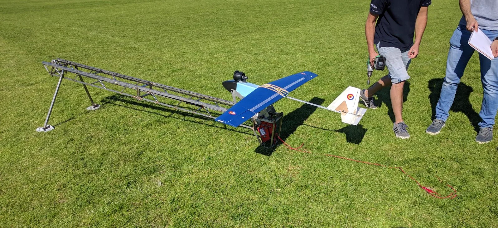
This project involved the design, manufacture and flight testing of a 1.8 m wingspan fixed-wing Unmanned Aerial Vehicle (UAV), developed as a second-year MEng group design project. Starting with only an empty fuselage and tail assembly, the team was tasked with developing the aircraft’s wing, avionics system and flight control architecture from the ground up. The objective was to create a lightweight, reliable and aerodynamically efficient aircraft capable of stable flight while satisfying strict constraints on size, weight and manufacturability.
My primary responsibility was the mechanical design and CAD of the wing, translating the team’s aerodynamic and structural parameters into a manufacturable model. I also performed the aircraft’s static stability analysis and designed the slotted flap deployment mechanism. During the build and test phases, I coordinated manufacturing activities and supported the integration and validation of the complete aircraft.
2. Concept Development and Aerodynamic Design
2.1. Design Requirements
The project imposed several design constraints, including a maximum envelope of 0.9 × 0.25 × 0.3 m for each wing half, a strict mass budget of 1.5 kg, and the requirement to integrate telemetry and autopilot capabilities. These limitations forced the team to balance aerodynamic performance, structural integrity and manufacturing practicality throughout the development process.
The primary aerodynamic objective was to maximise the aircraft’s usable speed range across a Reynolds number range of approximately 120,000 to 350,000, with a catapult take-off speed of 12 m/s. This required a wing capable of generating efficient lift at low speeds while maintaining low drag during higher-speed flight. To achieve this, extensive trade-off studies were performed covering airfoil selection, wing geometry, aspect ratio, taper ratio and high-lift devices.
2.2. Airfoil and Wing Optimisation
A detailed aerodynamic study was carried out using XFLR5 and other airfoil analysis tools. Several low-Reynolds-number airfoils were investigated before finally settling on the NACA 4412, whose 12% thickness-to-chord ratio and 4% camber sat comfortably inside the target bands of 10 to 15% and 3 to 5% that the trade studies had converged on, balancing profile drag, stall angle and the internal space the structure needed. The runner-up candidate, the Selig-Donovan SD7032, was ultimately rejected as it would be too thin to meet the required structural stiffness and, on the XFLR5 comparison, offered no aerodynamic advantage to offset it.
The final wing geometry was refined iteratively in simulation to improve lift distribution and reduce induced drag, working through taper ratio, aspect ratio and control surface sizing. The most consequential change was to the taper: dropping it from 0.7 to 0.65 lifted the wing’s aerodynamic efficiency by 1.6% and took weight out of the tips, where it mattered most for roll response.
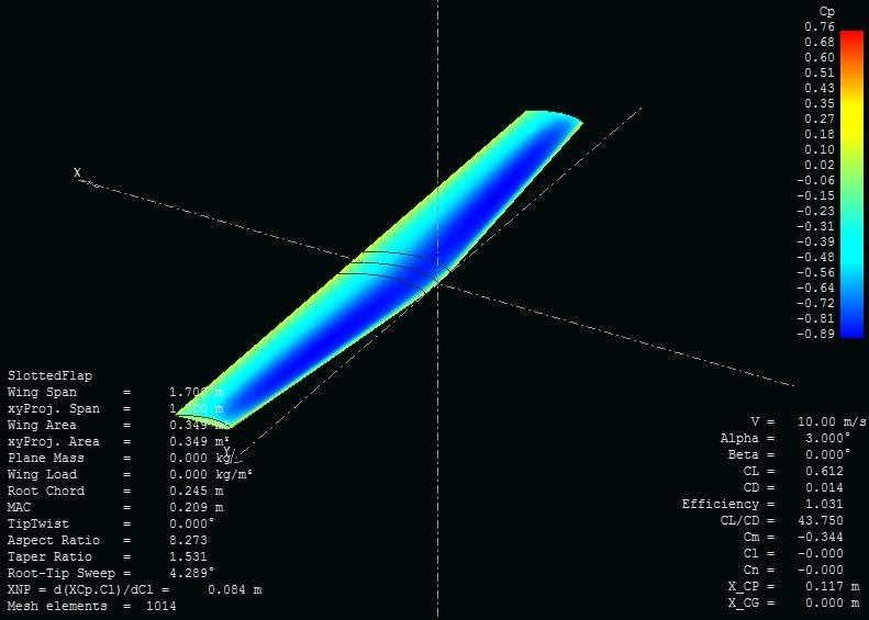
The lower bound on taper was set as much by manufacturing as by aerodynamics. A sharper taper forces the hot-wire cutter to travel much further at the root than at the tip in the same pass, and the slower wire melts and deforms the foam surface. At 0.65 the workshop technician was confident the sections would come out clean, and a more aggressive taper would in any case have made the wing easier to tip-stall.
The ailerons, sized against the same simulations, spanned 300 mm, around a third of the half-span, with a maximum deflection of ±25°.
2.3. Static Stability Analysis
The aircraft was designed with stability as a key objective. I calculated the static margin using analytical formulas, combined with lift-curve slope and geometry data obtained from XFLR5’s Vortex Lattice and 3D Panel analysis. Targeting a static stability margin of at least 15% for robust handling across a range of conditions, I positioned the wing as far rearward as the design allowed, achieving a static margin of 22.5%, comfortably exceeding the target and resulting in strong inherent longitudinal stability.
Lateral stability was less of a concern for the team, since the high-wing configuration conferred passive stabilisation through the moments generated by skin friction drag during sideslip, complemented by the effective sweep introduced by the wing’s taper.
3. Structural Design
3.1. Wing Architecture
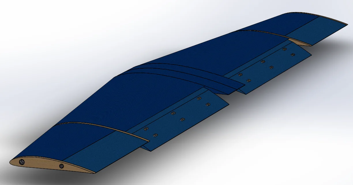
Once the conceptual design of the wing had been finalised, I modelled each individual component in CAD according to the defined aerodynamic and structural parameters, keeping manufacturability in mind throughout, then bringing them together into a single CAD assembly.
The final full wing design consisted of:
- Six CNC-cut Styrofoam wing sections
- Six laser-cut plywood reinforcement ribs
- Two front spars, a short rear joining spar and two aileron hinge shafts (all carbon fibre tubes)
- Two ailerons
- Two slotted flaps
- Solartex heat-shrink fabric skin
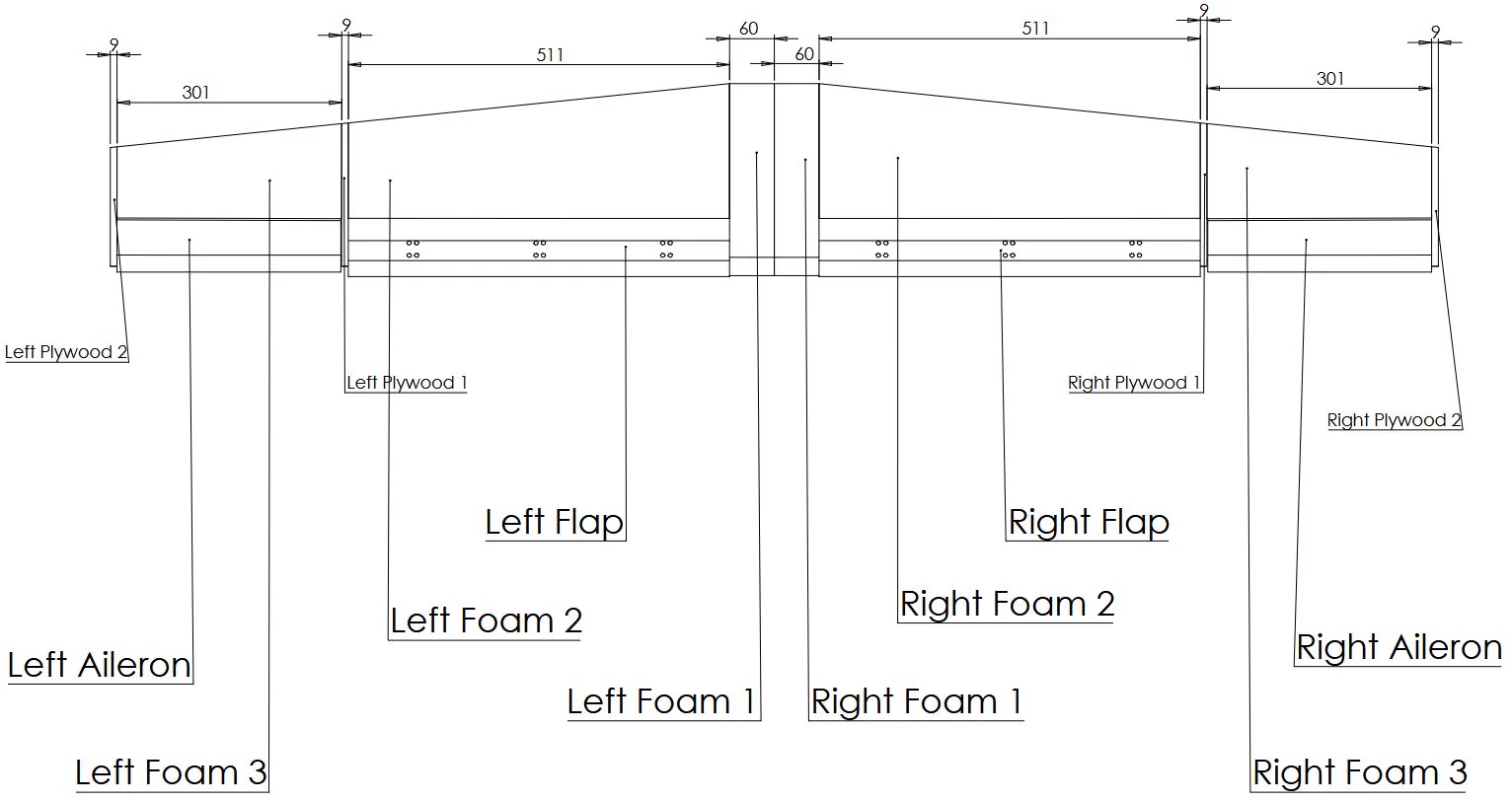
The foam sections were not solid. A cavity ran through the core of each one, tapering with the wing, to strip out material the structure did not need. How much could be removed was limited by the wall thickness left behind: below about 3.4 mm the sections became fragile enough to snap during handling or testing, and at the root the cutter’s taper limits left the lower surface as thick as 5.93 mm, more than the loads called for.
Together this made for a lightweight yet rigid structure, able to take both flight loads and the knocks of ground handling.
3.2. Carbon Fibre Spar System
A major part of the structural work focused on the spar arrangement. Carbon fibre tubes were chosen as the primary load-bearing elements due to their exceptional stiffness-to-weight ratio. The original front spar design ran along the wing’s tapered leading edge, meeting at a 3D-printed ABS joiner at the wing’s centre join, a joiner later found to concentrate stress dangerously at that point. To resolve this, the front spars were relocated rearward to a constant-chord section of the wing, reducing their length to 580 mm from an original 894 mm. The ABS joiner was also replaced with a machined aluminium tube (15 mm outer diameter, 10 mm bore) connecting both wing halves. Between the shorter run and the switch from pultruded to roll-wrapped rods, chosen because the wound fibres carry the torsion the leading edge sees far better than unidirectional ones, the front spar dropped from 37.8 g to 30 g per wing.
A short rear spar completed the centre join. The aluminium tube alone left the two halves free to rotate about it, so a second carbon tube, roughly 120 mm long, was slotted near the trailing edge across the two inner foam sections to lock them against each other. A late .dxf error that swapped the intended 8 mm tube for a 10 mm one ended up reducing the peak bending stress at the join from 17.8 MPa to 9.7 MPa, a welcome side effect of an otherwise unplanned change. The offcuts from the same metre of tube became the hinge shafts for the two ailerons.
3.3. Slotted Flap Development
One of the most interesting aspects of the project was designing the slotted flap deployment mechanism.
Unlike simple plain flaps, slotted flaps allow high-energy airflow from beneath the wing to re-energise the upper surface boundary layer. This delays flow separation and improves lift generation at low speeds, resulting in a considerably reduced stall speed and improved low-speed handling.
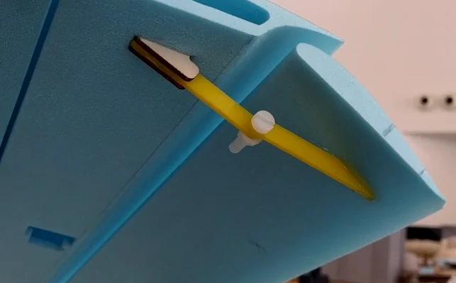
I designed and modelled the hinge components in CAD, then integrated them into the full wing assembly. Two hinges, positioned at each end of the flap span, supported the bending loads experienced in flight, complemented by a servo rod attachment at the flap’s midspan. I tested multiple hinge concepts before arriving at a solution that delivered sufficient strength and the deployment geometry the slot required.
The hinges themselves were built from acrylic and plywood parts bolted together, with one of the bolts forming the pivot. Acrylic was chosen for its stiffness and resistance to splintering under load compared to plywood, while nylon nuts and bolts were used throughout, pivot included, to save weight over steel fasteners.
The wing end of each hinge was originally intended to be held by four bolts alone, but they crushed the foam beneath them even with a load-spreading plate behind. Bonding that end was the obvious way out, provided the bond could be trusted to carry the flap loads on its own.
To check that, I tested epoxy resin against hot glue by incrementally loading a test joint until failure: hot-glued joints failed at just 2.8 kg (1.4 kg per hinge), while epoxy-bonded joints held up to 6.2 kg before the surrounding foam itself gave way. Epoxy went onto the wing end alongside the bolts, which were left to locate the hinge rather than carry it. The result settled more than the adhesive: the original layout had called for three hinges evenly spaced along the flap, but with the epoxied joint holding until the foam around it failed, two proved to be enough.
4. Manufacturing and Assembly
4.1. Wing Construction
Following completion of the design phase, manufacturing began from the engineering drawings I had produced for the foam sections, plywood components and flap hinge mechanism.
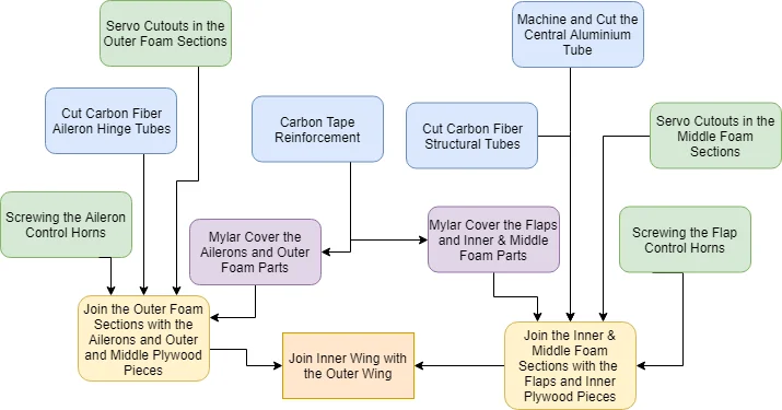
A university workshop technician produced the Styrofoam wing sections using CNC hot-wire cutting from these drawings, while I programmed the laser-cutting of the plywood structural components and hinge parts from the corresponding .dxf files.
Particular attention was given to maintaining dimensional accuracy during manufacturing, as even small geometric deviations could noticeably affect aerodynamic performance. Each foam section was checked against the drawings as soon as it came off the cutter, and the mirrored pairs turned out not to match exactly, a limitation of the hot-wire process rather than of the geometry. The longer parts were trimmed back by hand with a scalpel before assembly.
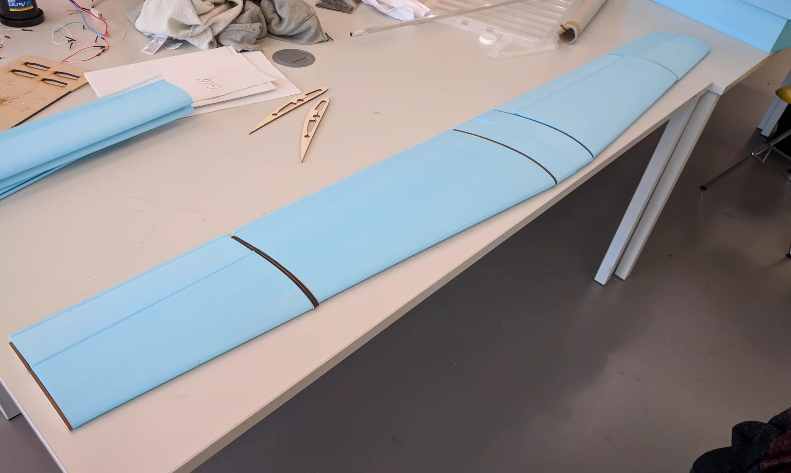
The wing sections were bonded together using epoxy resin and reinforced with Solartex, a heat-shrink fabric covering ironed on over the foam at a temperature high enough to shrink and bond the fabric but not to melt the Styrofoam underneath. In addition to improving durability, the covering contributed to the overall stiffness of the structure and created a cleaner aerodynamic surface.
4.2. Wing Structural Verification
Before final integration, the wing underwent structural verification to confirm it could withstand the loads expected in flight. FEA analysis of the wing structure confirmed that deflection would remain within acceptable limits under loads of up to 5g.
The wing was then subjected to a physical loading test: weight was incrementally added to the wingtip while measuring deflection, both to confirm the wing met the minimum load-bearing requirement and to obtain an experimental measurement of bending stiffness. The wing carried the required load without damage or permanent deflection, clearing the aircraft for flight testing.
4.3. Final Aircraft Integration
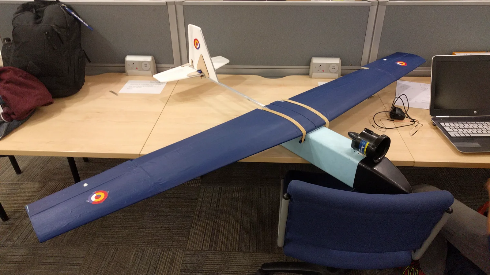
Once the wing was complete, I worked closely with another team member to integrate it with the fuselage, propulsion system and avionics package. Several iterations were required to optimise component placement and improve weight distribution.
Mounting the wing turned out to be the fiddliest part of the integration. The conventional method, rubber bands hooked over carbon retainers on each side of the fuselage, could not hold it still: the heat-shrunk covering was too slippery, and under load the wing vibrated and rotated slightly against the fuselage, which would have altered how the control surfaces loaded and behaved in flight. More bands would have added weight and risked crushing the fragile trailing edge, so a non-slip rubber mat was placed between wing and fuselage instead, which removed almost all of the movement. A thick plywood shim under the leading edge set the wing’s incidence relative to the fuselage.
This stage transformed the project from a collection of subsystems into a complete, flight-ready aircraft.
5. Avionics and Flight Control System
5.1. Electronics Architecture
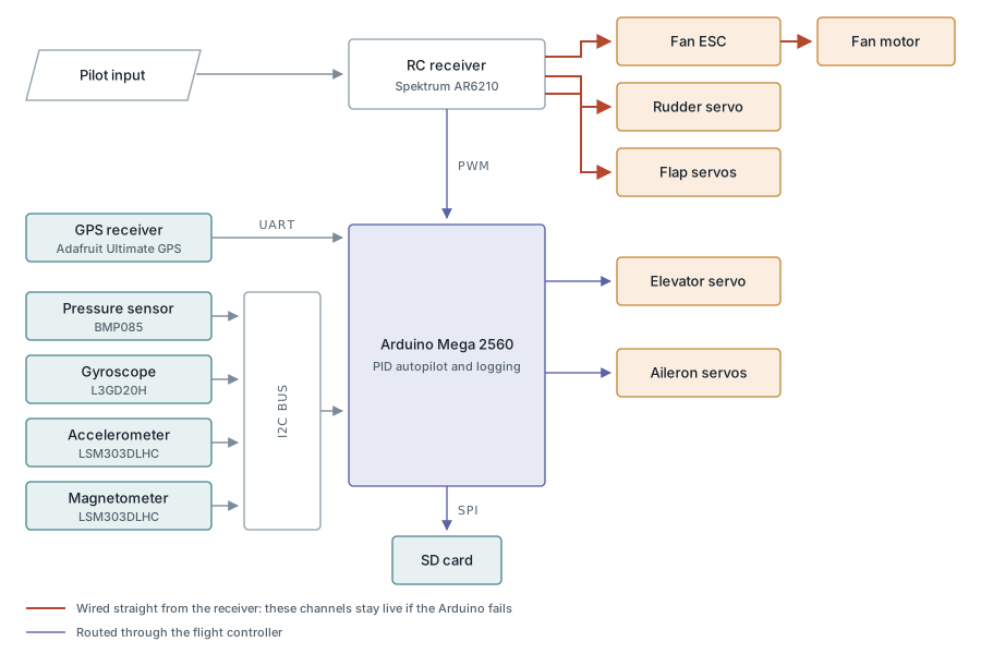
The aircraft featured a fully custom avionics system built around an Arduino Mega microcontroller. This replaced the initially planned Arduino Uno after development trials revealed its 2 KB of dynamic memory to be insufficient for the combined sensor, GPS, data-logging and PID autopilot code, while the Mega’s 8 KB gave the necessary headroom. The system was responsible for processing pilot commands, collecting sensor data and driving the elevator and aileron servos.
A wide range of sensors were incorporated into the aircraft, including:
- GPS receiver
- Barometric pressure sensor
- Three-axis accelerometer
- Three-axis gyroscope
- Three-axis magnetometer
All sensor data was recorded to an onboard SD card at a 1 Hz logging rate for post-flight analysis. This allowed flight performance, aircraft behaviour and sensor performance to be evaluated after the test flight.
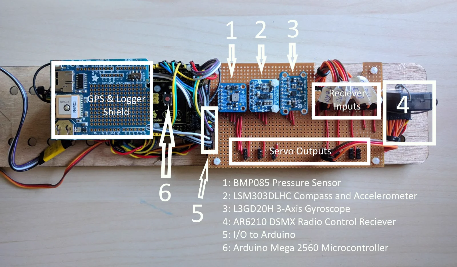
The sensors, receiver and controller all connected to a single custom soldered board acting as the wiring hub. It distributed power and the I2C sensor bus, and organised servo outputs and receiver inputs on opposite sides of the board for easy assembly and fault-finding, offering a flexible platform that could be expanded and modified throughout the project.
5.2. Autopilot Development
In addition to manual flight capability, the aircraft included a basic autopilot system based on PID control for roll and pitch stabilisation.
For safety, the throttle and rudder channels were wired directly from the receiver to the electronic speed controller and rudder servo, bypassing the Arduino entirely, so that a controlled descent remained possible even in the event of a full autopilot failure. The flap servos ran off the receiver too, on the reasoning that a high-lift device the autopilot never commanded had nothing to gain from passing through it. The controller was designed to assist with aircraft attitude stabilisation and reduce pilot workload during flight.
6. Flight Testing
6.1. Test Objectives
The final stage of the project was a single flight test of the complete aircraft, with the following objectives:
- Verifying flight handling and stability characteristics
- Measuring maximum and minimum flight speed
- Assessing autopilot reliability
- Evaluating telemetry and data logging performance
- Testing structural integrity under real flight conditions
6.2. Flight Performance Assessment
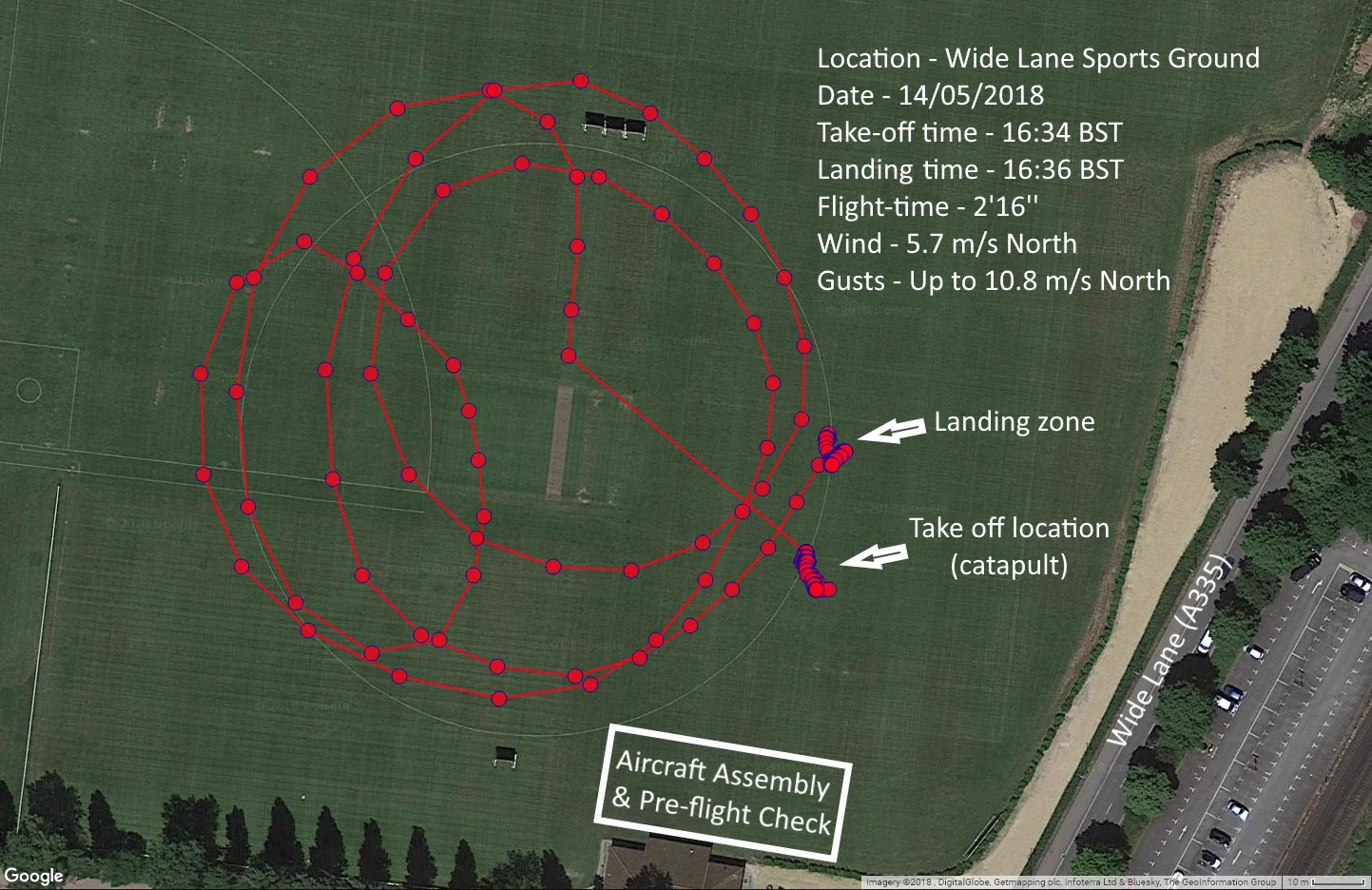
The test flight lasted 2 minutes and 16 seconds, flown in challenging weather conditions with wind speeds of 5.7 m/s and gusts of up to 10.8 m/s. Despite these conditions, the aircraft demonstrated stable and predictable flight characteristics.
Take-off was smooth and the aircraft required only small control inputs to maintain stable flight. The stability margins incorporated during the design process proved effective, and the aircraft exhibited the balance of manoeuvrability and robustness that the team had originally targeted, with no structural issues observed at any point during the flight.
Unfortunately, no data on the aircraft’s usable speed range, the project’s primary aerodynamic objective, could be collected: the pitot tube used to measure airspeed had been damaged beyond repair on a different team’s aircraft during their test flight earlier that day, with no replacement available.
The flaps were also absent from the flight. Play in the servo-to-flap linkage, combined with flex in the flap itself, made in-flight deployment a flutter risk, so the capability was disabled to guarantee a safe flight and a clean data set. The minimum flight speed achieved was therefore higher than the wing had been designed for. The fix identified afterwards was straightforward: a spar running through the flap to reduce flex, and the servo moved further forward to shorten the pushrod.
The autopilot got even less of a chance. It was engaged briefly in the air, and a gust caught the aircraft almost immediately: the nose dropped towards the ground and control went straight back to the pilot, with no appetite to try again on the only flight available. The PID gains had been chosen by educated guesswork rather than derived from anything, and a gusty afternoon was not the place to start tuning them.
6.3. Telemetry Analysis
The onboard logging system successfully recorded sensor data throughout the flight.
Magnetometer data showed strong, synchronous patterns during the aircraft’s turns, with seven distinct rolling manoeuvres clearly identifiable in the log, confirming the telemetry system’s ability to capture real flight dynamics.
Pressure sensor readings traced the aircraft’s altitude profile, showing periods of steady altitude interspersed with climbs, and a sharp rise consistent with the aircraft’s first landing approach partway through the flight.
GPS data closely matched the flight path observed on video, correctly capturing the aircraft’s circular pattern over the test site, though not for the whole flight: the receiver lost its fix for around 86 seconds on the ground and only regained it after the first lap, leaving roughly 50 seconds of the track unrecorded. The satellite count and GPS altitude fields logged as zero throughout, traced to a data type conversion error in the logging code rather than a hardware fault.
Gyroscope readings sat around zero for most of the flight, as expected of an aircraft that was never rotating quickly, with slow ramps in the X and Y channels marking the banked turns and no comparable signature in yaw.
Accelerometer data proved largely inconclusive, as the combination of gravitational, manoeuvring and gust-induced accelerations in dynamic flight was too complex to interpret cleanly, and derived roll/pitch estimates were undermined by the assumption of steady level flight, which did not hold given the gusty conditions.
6.4. Flight Demonstration
The successful flight represented the culmination of the entire design, manufacturing and testing process. It validated the structure and the avionics as a data-gathering platform, even if the aerodynamic objective that had driven the wing design went unmeasured and the autopilot was left unproven.
Footage from the test flight, showing the catapult launch, stable cruise and landing approach, is included below:
7. Conclusions
This project provided a complete introduction to the multidisciplinary nature of aircraft development, covering the entire engineering lifecycle from initial concept generation through to flight testing.
My contribution centred on the CAD and mechanical design of the wing, the aircraft’s static stability analysis, and the design of the slotted flap deployment mechanism, complemented by the manufacturing drawings, coordination and final integration work of the aircraft. The resulting UAV flew stably and predictably in conditions well outside the ideal, and the wing carried it without complaint. The one piece that never got its chance in the air was the flap mechanism, grounded by the play in the linkage that drove it, the one part of the mechanism that never saw a load test.
Beyond the technical achievements, the project offered valuable experience in teamwork, leadership, problem-solving and systems engineering, closely reflecting the challenges encountered during the development of real-world aerospace vehicles.