1. Introduction
Project Sirius was my final-year Group Design Project as part of the MEng Aerospace Engineering programme at the University of Southampton.
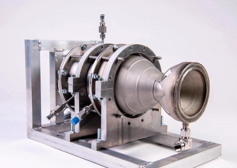
The project formed part of a multi-year effort to develop and experimentally fire a regeneratively cooled bipropellant rocket engine using High-Test Peroxide (HTP) and turpentine. The engine featured a 3D-printed Inconel combustion chamber and nozzle and was designed to produce approximately 1.5 kN of thrust. Our objective during the 2019-2020 academic year was to prepare the engine and its supporting systems for their first full-scale firing campaign.
2. Engine Architecture
The Sirius engine uses High-Test Peroxide (HTP) as an oxidiser and turpentine as fuel. HTP is an increasingly attractive propellant choice for spacecraft and small launch vehicles, offering a safer and more environmentally friendly alternative to conventional hypergolic propellants.
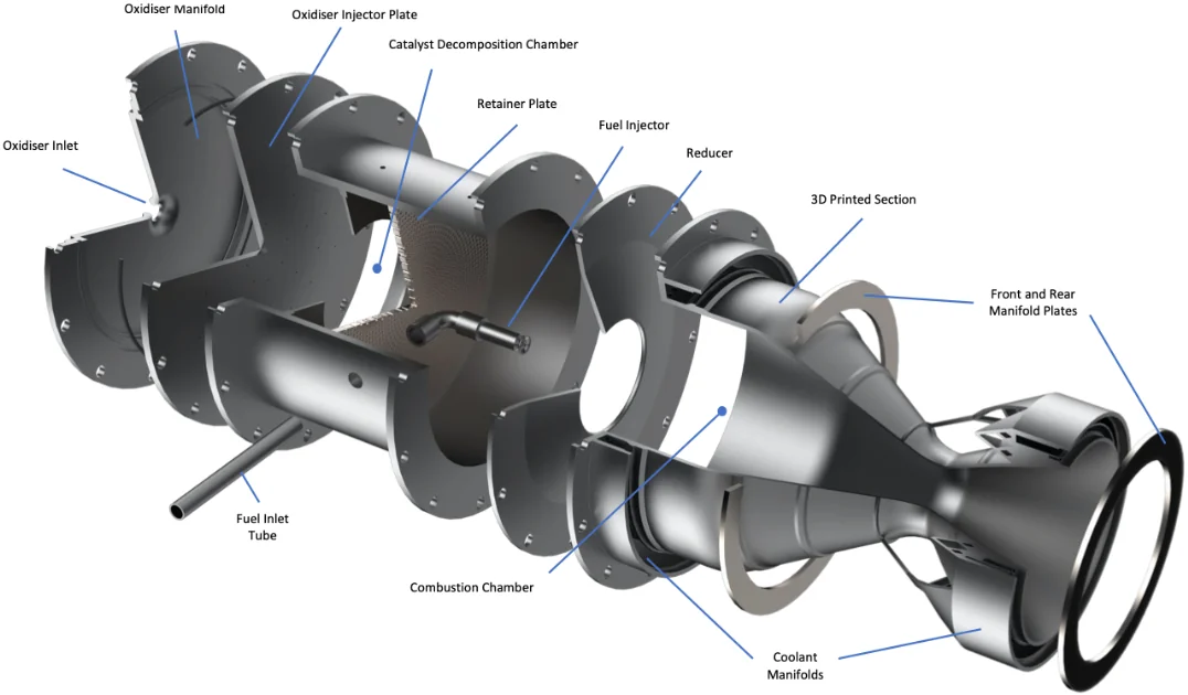
During operation, liquid peroxide first flows through the regenerative cooling channels integrated within the combustion chamber and nozzle walls. This process removes heat from the engine and pre-heats the oxidiser before it is injected into the catalyst decomposition chamber. Inside the decomposition chamber, a manganese oxide-based catalyst decomposes the HTP, generating hot gaseous oxygen and steam.
The decomposed oxidiser is then accelerated through a reducer before entering the combustion chamber. Turpentine is injected downstream through a swirl injector, where it mixes with the hot decomposition products and ignites spontaneously. The resulting combustion gases expand through the converging-diverging nozzle to generate thrust.
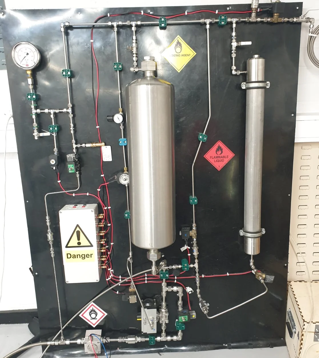
The engine is supported by a dedicated propellant delivery system, instrumentation and control software responsible for supplying propellants, regulating flow and acquiring test data during experimental testing.
3. Project Context
Project Sirius consisted of several parallel development streams that collectively aimed to prepare the engine for its first full-scale firing campaign.
Across the team, work spanned catalyst qualification, injector development, propellant delivery hardware, control software, wet testing, nozzle repair studies and preparations for the planned firing campaign.
My work focused primarily on catalyst validation and oxidiser injection system development, where I took full ownership of the design and validation activities. I also redesigned combustion-system hardware and manufactured a large share of the catalyst inventory required for the planned firing campaign. I later contributed to the investigation of a critical manufacturing defect discovered in the engine nozzle shortly before the planned testing date. Alongside these technical responsibilities, I acted as lead editor for the group’s final report and project video.
The chapters that follow detail each of these contributions in turn, starting with catalyst validation.
4. Catalyst Validation
4.1. Developing a Representative Validation Methodology
One of the most important technical questions facing the project was whether the internally developed catalyst could reliably decompose HTP at the operating conditions required by the full-scale engine. Previous teams had demonstrated promising catalytic performance, but validation at the target catalyst bed loading had not yet been achieved.
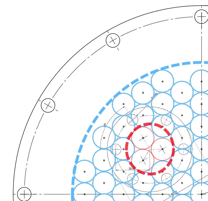
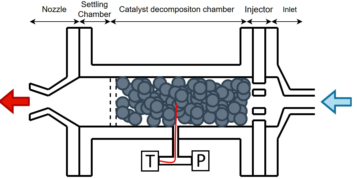
Closing that gap meant making the small-scale test hardware genuinely representative of the full-scale chamber, and I built the redesign around the scaling approach the project referred to as the tubule model. The model treated each injector hole as an individual flow region with its own area of influence within the catalyst bed. By preserving local catalyst loading and injector configuration, a smaller decomposition chamber could reproduce the key operating conditions of the full-scale engine.
4.2. Redesigning the Validation Hardware
With no CAD records available for the inherited small-scale injectors from previous project years, I first had to measure their geometry directly, using digital callipers and a microscope, which revealed hole dimensions that differed substantially from those of the full-scale injector.
Rather than scaling the hardware geometrically, the design process therefore focused on preserving the parameters that govern catalyst performance: catalyst bed loading, catalyst bed length and injector characteristics. These requirements drove the redesign of both the injector and nozzle.
The injector was developed to replicate the oxidiser distribution and local catalyst loading of the full-scale chamber, while the nozzle was resized to lower the design chamber pressure from 10 bar to 3 bar. Because the decomposition of liquid peroxide is largely insensitive to pressure in this range, this could be done without making the test any less representative, and it cut the nitrogen supply pressure needed to reach the target mass flow rate by around 7 bar, keeping the laboratory rig well inside its safe limits. The throat was sized from the characteristic velocity of the decomposition products, and the resulting area ratio was cross-checked against NASA CEA, which agreed to within about 0.5%.
The resulting hardware provided a representative test platform that allowed catalyst performance to be validated.
4.3. Experimental Validation Campaign
Following the design and manufacturing effort of the small-scale thruster, eight test firings were conducted over two days of testing at the university. Performance was evaluated using chamber-pressure measurements, chamber-temperature measurements and mass-flow calculations derived from test data.
The first test campaign reached a maximum bed loading of approximately 38 kg·s⁻¹·m⁻², short of the 50 kg·s⁻¹·m⁻² target. It also produced two runs in which the chamber thermocouple dropped abruptly to near ambient. Chamber pressure held steady throughout and no liquid was seen leaving the nozzle, so rather than flooding, the readings were attributed to the position of the probe: the fitting at the bed exit plane was blocked, so the thermocouple sat partway along the bed, where peroxide that had not yet fully decomposed could still reach it.
Two things stopped the campaign there. Extrapolating the data showed that reaching the target would demand line pressures above the safe rating of the propellant delivery rig, and the volume of steam leaving the nozzle was filling the test cell faster than the extraction duct could clear it. A sleeve insert was therefore introduced to reduce the cross-sectional area of the catalyst bed, raising bed loading for a given mass flow rate: the target could then be reached at a lower mass flow, and with far less plume.
The second campaign, conducted with the reduced-area chamber, achieved bed loadings approaching 60 kg·s⁻¹·m⁻² while producing decomposition temperatures above 600°C, demonstrating complete peroxide decomposition and validating the catalyst for use in the full-scale engine.
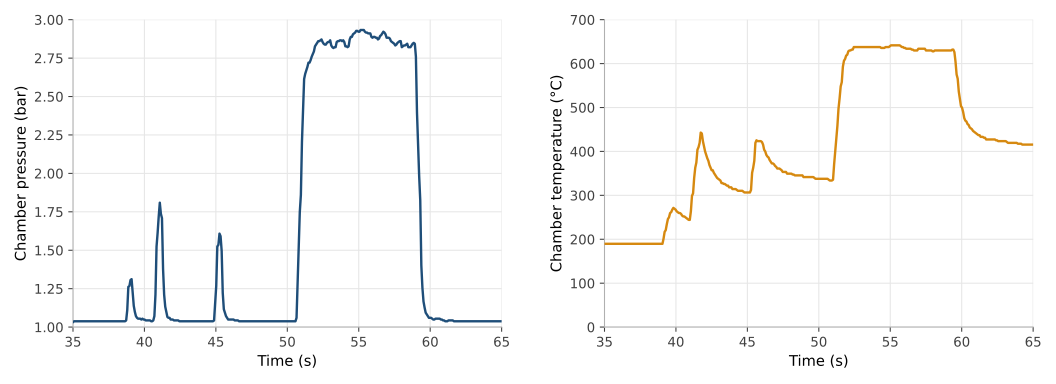
This milestone removed one of the major technical uncertainties associated with the planned firing campaign, providing confidence in the decomposition chamber design ahead of full-scale testing.
5. Oxidiser Injection System Development
While the catalyst validation programme focused on proving catalyst performance, it also highlighted the importance of achieving uniform oxidiser distribution across the catalyst bed.
The oxidiser injector inherited from previous project iterations used a different geometry from the validation hardware and provided a less uniform flow distribution than desired. This limited the applicability of previous testing campaigns and introduced uncertainty when extrapolating results to the full-scale engine.
To address this issue, I redesigned the oxidiser injector used in the full-scale engine from first principles, with the objective of improving flow distribution while maintaining consistency with the validation hardware and ensuring the design remained manufacturable.
5.1. Design Objectives
The oxidiser injector plays a critical role in determining how peroxide is distributed across the catalyst bed. Non-uniform injection can lead to localised overloading, uneven decomposition and reduced catalyst utilisation, making injector design a key factor in overall engine performance.
The redesign was therefore driven by four primary objectives:
- Improve oxidiser distribution across the catalyst bed.
- Maintain consistency between the sub-scale and full-scale systems.
- Achieve a geometry that could be reliably manufactured.
- Keep plate deflection small enough not to crush the catalyst pellets sitting directly beneath it.
These requirements often competed with one another. Increasing injector plate thickness improved stiffness but constrained the achievable injector geometry and increased component mass, while thinner plates enabled smaller injector features but were more susceptible to deformation under pressure.
5.2. Injector Design and Analysis
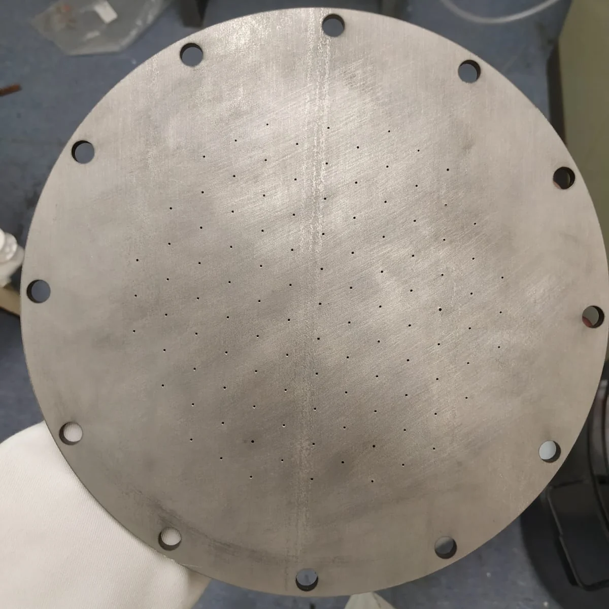
The new design adopted a hexagonal hole distribution pattern, ensuring that each injector element influenced a similar area of catalyst bed. Compared to the inherited design, this provided a significantly more uniform distribution of oxidiser across the decomposition chamber.
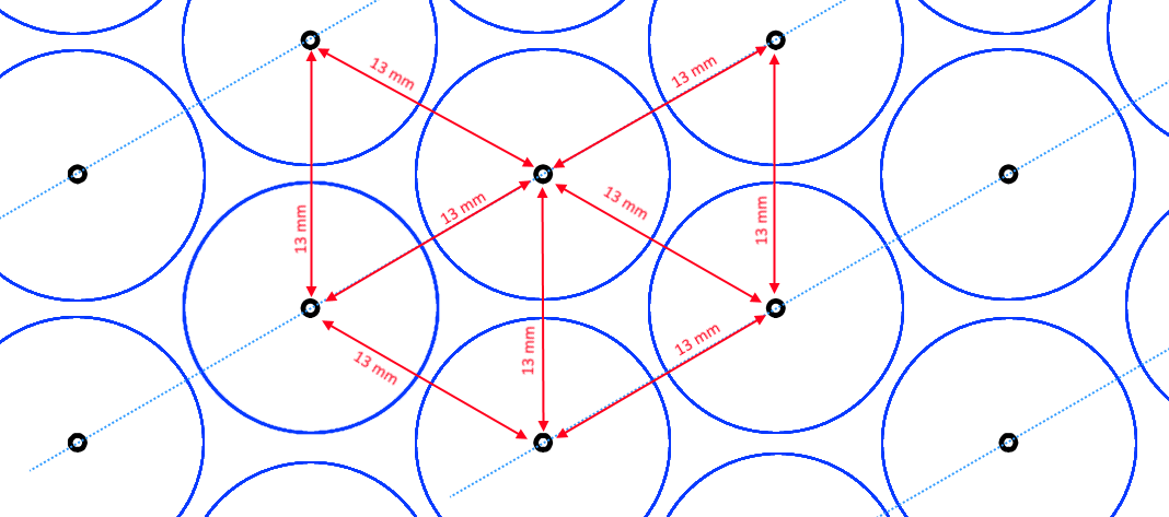
Injector pressure drops in production engines typically sit at 20 to 30% of chamber pressure. At the 10 bar chamber pressure of Sirius that pointed to roughly 2 to 2.5 bar, and a safety margin was added on top to give 3.5 bar, trading a higher required feed pressure for a wider margin against pressure oscillations propagating upstream.
Plate thickness was the second key design variable. To identify an appropriate value, I combined analytical plate-deflection calculations and finite element analysis models.
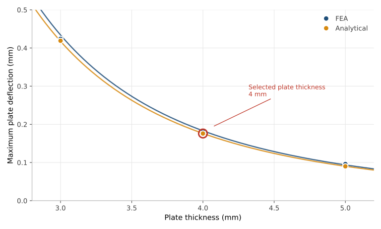
Balancing these factors led to the selection of a 4 mm thick injector plate. At 4 mm the predicted deflection under the injection pressure drop is around a twentieth of the characteristic length of a gamma-alumina pellet, small enough to be harmless, while 3 mm more than doubles it. The workshop could only supply 316L sheet in 1 mm increments, so the real choice was between 3, 4 and 5 mm. Four millimetres cost 0.1 mm of extra deflection compared with the inherited 5 mm plate, but it brought the minimum drillable orifice down to 0.66 mm, since drilling depth should not exceed about six times the bit diameter. With a 0.7 mm drill and the 3.5 bar design pressure drop, the final plate carried 109 orifices, marginally fewer than the 111 the calculation asked for, since that was the most the pattern could fit inside the chamber walls, which cost less than 1% of the theoretical bed loading.
During manufacture, four drill bits snapped inside the plate and had to be spark eroded out from the opposite face, leaving those four holes slightly oversized on one side. Rather than requiring a full re-manufacture, the affected plate was oriented so that these defects faced the oxidiser manifold rather than the catalyst chamber, allowing the injector to remain fit for use within the required tolerances.
Once manufactured, the full-scale injector was drop tested with HTP across several spots on both faces to confirm it was compatible and did not need further cleaning. No reaction was observed.
5.3. Experimental Characterisation
Following manufacture, the injector performance was experimentally characterised through cold-flow testing of the small-scale thruster injector using deionised water. Both plates shared identical orifice geometry, so the discharge coefficient measured on the small-scale injector applies directly to the full-scale one.
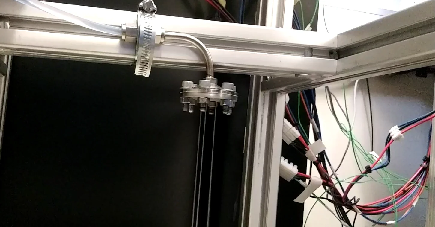
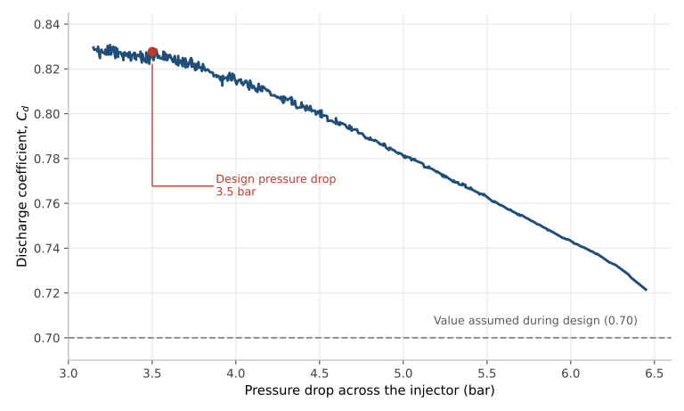
Mass flow rate measurements were collected across a range of operating pressures and used to determine the injector discharge coefficient. The results were then compared against the assumptions used during the design process.
The measured discharge coefficient came out approximately 17% higher than the assumed value. This discrepancy was most likely a measurement artefact. The oxidiser manifold had no port for a pressure transducer, so the only reading available came from the rig upstream of the injector, where the transducer measured static rather than stagnation pressure. On narrow tubing not designed for the flow rates involved, that reading would understate the true pressure at the injector face, and an understated pressure drop translates directly into an overstated discharge coefficient.
A follow-up test using the full-scale injector and the full-scale propellant delivery system was planned to resolve this discrepancy, but could not be carried out due to the COVID-19 closure of the University. The injector’s hydraulic performance was therefore characterised at small scale but not conclusively verified at full scale.
6. Combustion System Optimisation
Catalyst decomposition and oxidiser distribution were critical to engine operation, but the flow conditions at which the decomposed oxidiser entered the combustion chamber also influenced combustion performance.
6.1. Combustion Chamber Inlet Conditions
Earlier research by one of the project supervisors had established that there is an optimal velocity at which the decomposed oxidiser should enter the combustion chamber, one that maximises the vaporisation of the incoming fuel droplets through forced convective heating and, with it, the rate at which combustion proceeds.
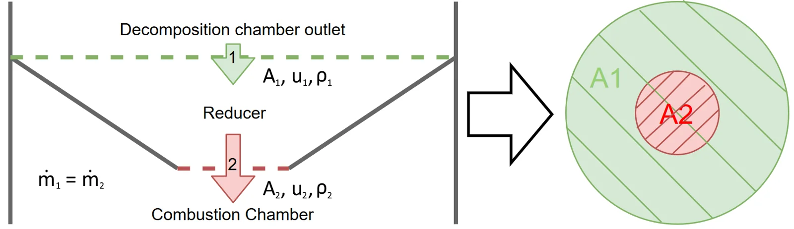
Achieving this target required redesigning the reducer section connecting the catalyst decomposition chamber and combustion chamber. The reducer inherited from the previous project year no longer met that target, because it had been sized around a fuel injector of a different diameter. Since the injector protrudes through the outlet plane of the reducer, its footprint has to be added to the required flow area, so a change of injector propagates directly into the outlet geometry.
6.2. Reducer Redesign
To achieve the desired inlet conditions, I redesigned the reducer using conservation-of-mass calculations together with thermodynamic properties obtained from NASA CEA analysis.
The objective was to accelerate the decomposed oxidiser to the target velocity while remaining compatible with the selected fuel injector and overall engine geometry. By modifying the reducer outlet area, the flow velocity entering the combustion chamber could be adjusted without introducing significant changes elsewhere in the propulsion system.
Although a simple component, the reducer sets the flow conditions the combustion process depends on. I produced the engineering drawings for the redesigned part and coordinated its manufacture, and the finished reducer was ready for integration into the full-scale engine.
7. Catalyst Manufacturing
The engine catalyst was based on manganese oxides deposited onto gamma-alumina support pellets.
Following the successful validation of the catalyst decomposition chamber, the next challenge was manufacturing sufficient catalyst for the planned full-scale firing campaign.
While catalyst development had been conducted at laboratory scale in previous years, the full-scale engine was expected to need well over a kilogram of catalyst pellets to completely fill the decomposition chamber. Scaling production from experimental batches to engine-scale quantities therefore became an important part of the project.
7.1. Scaling Production
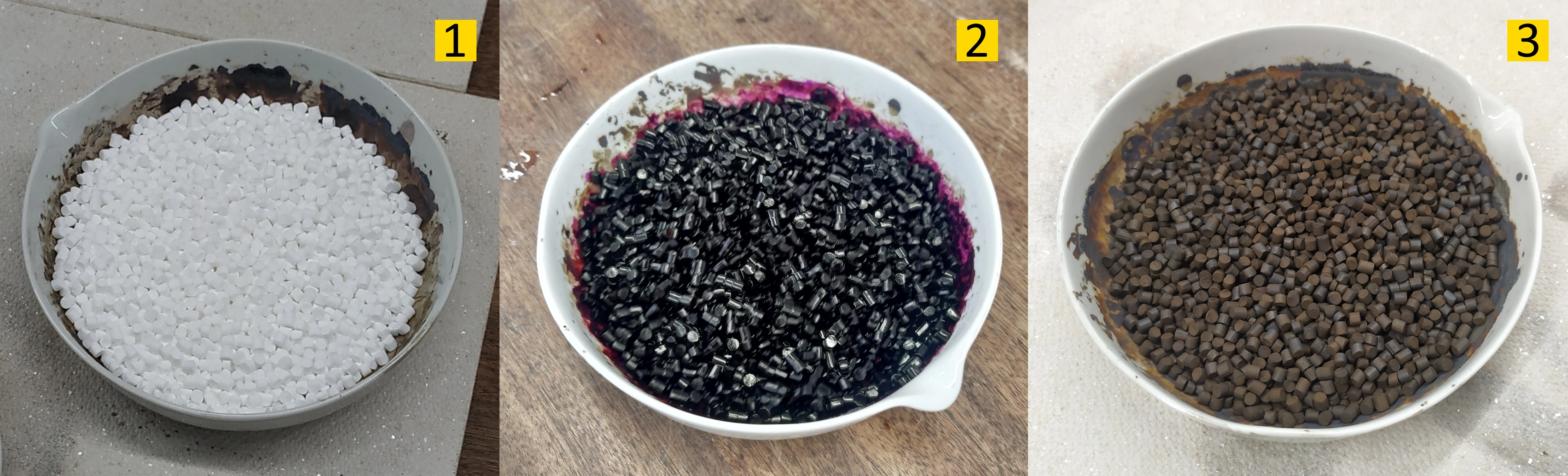
Catalyst production involved a lengthy process that included calcination, chemical impregnation, thermal treatment and quality assurance testing.
Over the course of the project, I personally manufactured about 580 g of catalyst across eight production batches, representing half of the catalyst inventory ultimately prepared for the full-scale engine. Each batch was weighed after every processing step to monitor consistency, with the resulting quality data used to track process repeatability throughout the campaign.
The data revealed that the impregnation solution loses potency quickly once used. Batches made with virgin solution took up 53 to 54% of their own mass in catalyst, against 33 to 44% for the earlier batches, which had been made with solution carried over from previous runs. The later batches used only virgin solution, and I recommended against reusing it in future production runs.
Producing eight batches also required careful planning around the limited furnace capacity available at the university’s high-temperature laboratory. Calcination and thermal treatment cycles were lengthy, reaching temperatures of up to 500°C. Coordinating batch schedules around this constraint made personal time management a challenge.
7.2. Verification and Loading
Producing the catalyst was only half the problem. Each batch had to be shown to work before any of it went near the engine.
Every batch was verified experimentally through HTP drop tests on sample pellets, which I carried out alongside another team member, confirming consistent catalytic reactivity across batches before the catalyst was cleared for use.
Filled and settled on a vibration table, the decomposition chamber took 850 g, less than originally estimated, leaving over 300 g of spare catalyst available for further experimentation.
8. Investigation of a Critical Nozzle Manufacturing Defect
Only weeks before the planned firing campaign, a major issue was discovered during testing of the engine cooling system.
Water introduced into the regenerative cooling channels was found leaking directly through the nozzle throat wall. Initial investigations revealed that the problem was far more severe than a simple sealing issue, with a significant proportion of the coolant flow escaping through the nozzle wall instead of staying in the cooling circuit. This immediately became one of the highest-priority technical risks facing the project.
8.1. Root Cause Investigation
Further testing and design reviews suggested that the defect originated from porosity within the additively manufactured Inconel nozzle.
The issue was concentrated around the throat region, where the wall separating the cooling channels from the gas path was only 0.25 mm thick, against a laser melting resolution of about 0.5 mm. The manufacturer later confirmed that walls below 0.5 mm were rarely achievable, which suggests the requirement and the process capability were never properly reconciled. As a result, coolant was able to pass through the nozzle wall rather than remaining within the intended cooling circuit.
With a firing campaign approaching, the challenge was no longer simply understanding the defect, but identifying a practical method of mitigating it without requiring a complete redesign and remanufacture of the engine.
8.2. Evaluation of Repair Strategies
Following the discovery of the defect, I joined the investigation effort and contributed to the assessment of several potential repair strategies.
The options considered included:
- Re-manufacturing the nozzle.
- Hot isostatic pressing.
- Ceramic barrier coatings.
- Physical or chemical vapour deposition.
- Phenolic ablative coatings.
- Operating the engine without modification.
Each option was evaluated against manufacturing complexity, schedule impact, technical risk and expected performance. While a complete re-manufacture would likely eliminate the defect, it was ultimately impractical within the available project timeline and budget.
Vapour deposition would have produced a uniform metallic layer, but applying it inside the confined geometry of the nozzle was impractical, and an ablative coating would have needed more development than the schedule allowed. On hot isostatic pressing, I consulted researchers in the Materials department with experience in metal additive manufacturing, who advised that the process closes microscopic porosity but would not address defects on the scale we were dealing with.
Following this trade study, the team selected barrier coatings as the preferred repair strategy, and I was tasked with identifying and shortlisting suitable candidate compounds ahead of testing.
8.3. Experimental Evaluation of Ceramic Coatings
Having already worked extensively with the university’s high-temperature furnaces during catalyst manufacture, I worked alongside another team member to evaluate the shortlisted candidate coatings experimentally.
Compatibility came first: both candidates were drop tested with HTP and then fully submerged in it, since a coating that decomposes peroxide on contact would be worse than no coating at all. Neither produced any appreciable reaction.
The programme then assessed adhesion, application behaviour and performance under thermal cycling representative of engine operating conditions. The objective was to identify a coating capable of sealing the porous regions while remaining mechanically stable during operation.
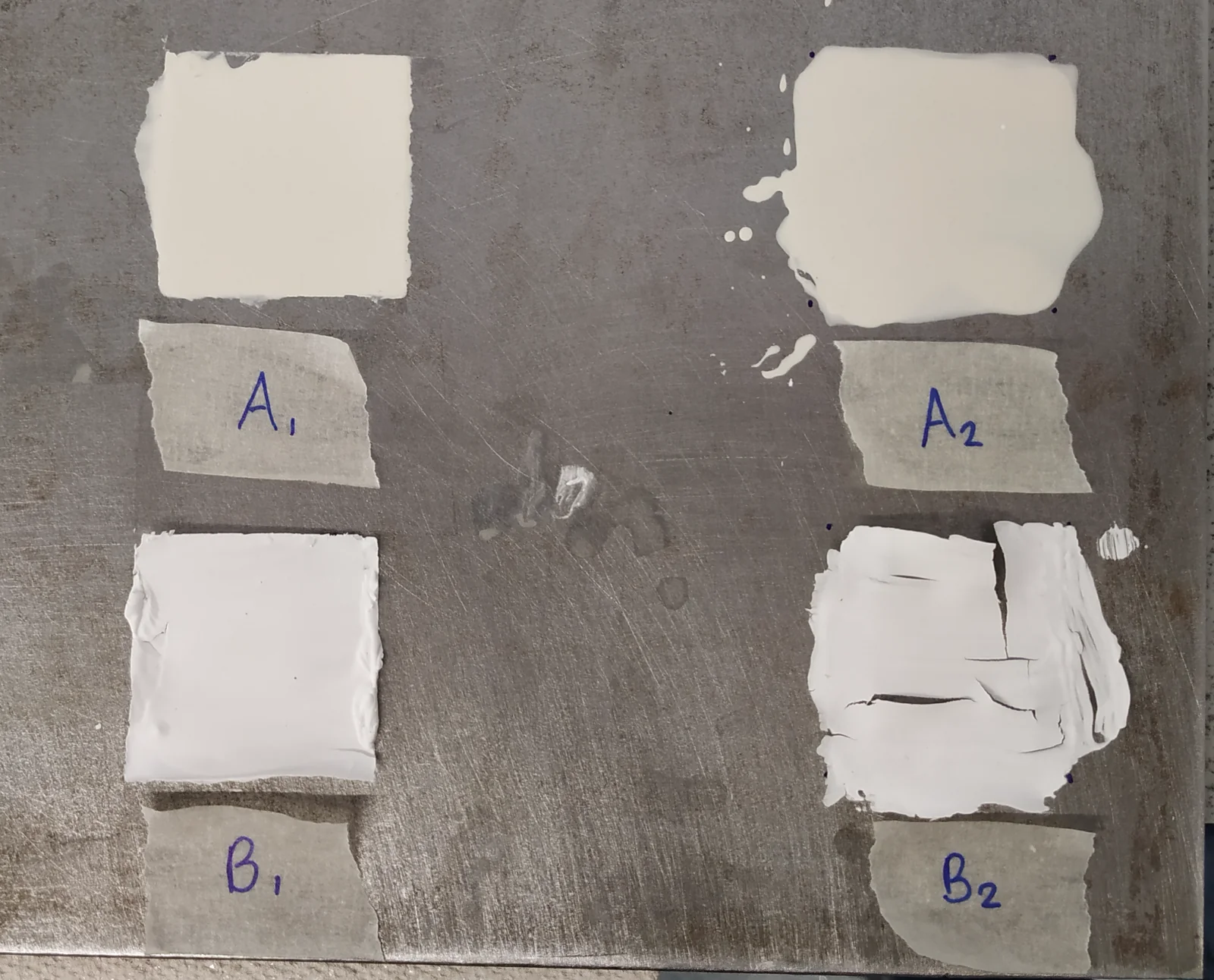
The testing programme confirmed the zirconium-oxide based coating I had put forward as the most promising candidate. The coating outperformed the alternative solutions evaluated in both adhesion and thermal performance, and was therefore selected as the preferred mitigation strategy.
The coating was applied to the interior of the nozzle before the university closed, but the leak test that had exposed the defect could not be repeated, so the repair was never verified. The firing objective had already been revised when the leak was first found, since bipropellant operation over an unsealed cooling circuit was not acceptable, and one of the project supervisors concluded that while the repair should be adequate for a monopropellant run, it should not be relied upon for bipropellant operation without further testing. The work established a credible path forward rather than a proven fix.
9. Preparing for Full-Scale Testing
By the final stages of the project, the major engine subsystems had been validated and manufactured, and the wider team had completed development and wet testing of the propellant delivery system. The focus shifted to what a firing campaign needs beyond hardware: a site, procedures, and the documentation to satisfy both.
9.1. Securing a Test Site
The full-scale engine was too large to be fired within university facilities, which had no suitable test cell, so the campaign depended on finding an external site able to support peroxide rocket engine operations. Following the assessment of several candidates, a test site was secured within one of the UK’s most historic rocket propulsion centres. The location provided dedicated test infrastructure, nearby propellant storage and the safety provisions required for liquid rocket engine operations.
9.2. Documentation and Logistics
An external campaign brings a documentation load of its own. The team produced the safety documentation, test plans, operating procedures and risk assessments required by the candidate facilities, covering the team, the propulsion hardware and the test procedures themselves.
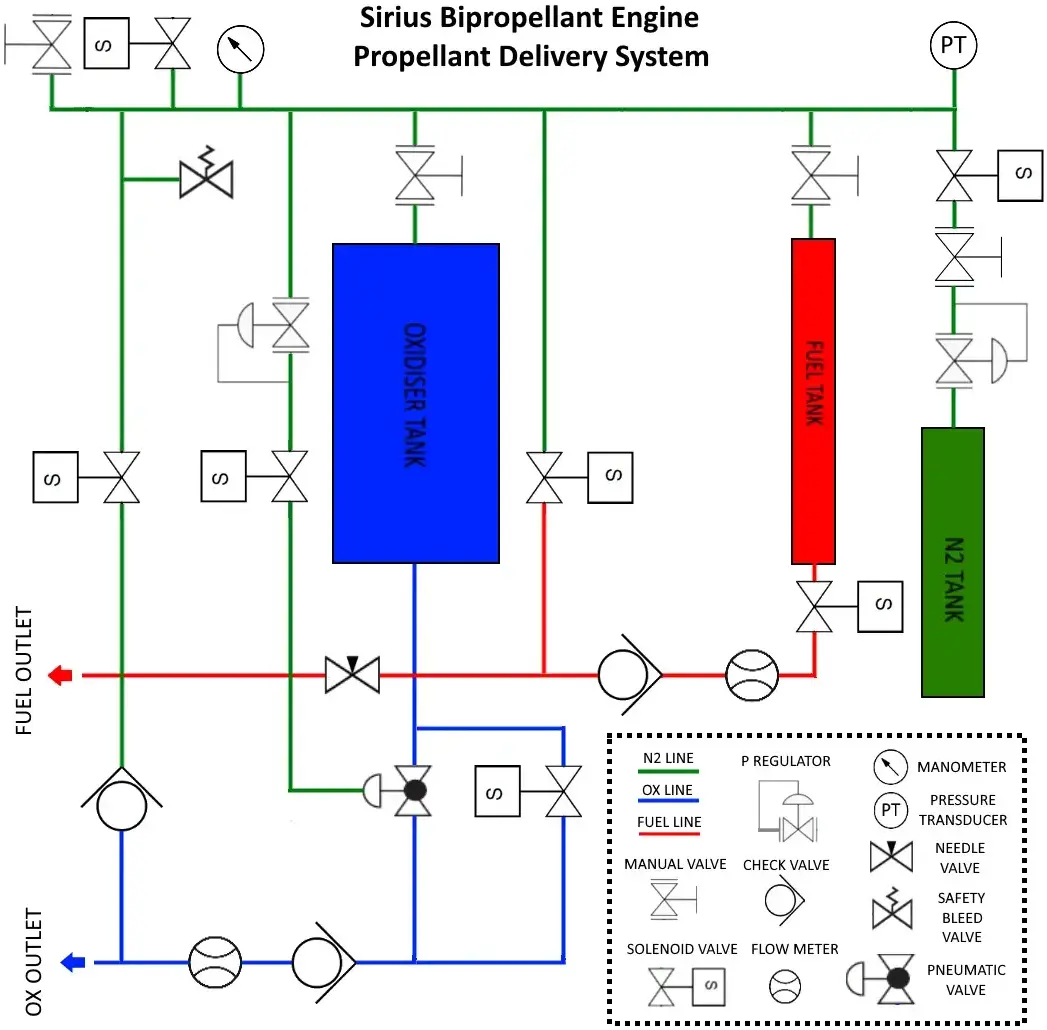
I contributed to that package and produced a schematic diagram of the propellant delivery system reflecting its configuration at the time, which was used to support the facilities’ review of the proposed campaign. I also took on the logistics of moving the engine, the propellant delivery system and the team to the site.
10. European Space Propulsion Conference 2020
As part of the project’s external communication activities, I authored the abstract submitted to the European Space Propulsion Conference (ESPC 2020).
The submission was accepted for presentation in Estoril, Portugal, in October 2020, under the conference’s liquid propulsion systems for launchers and upper stages category, providing an opportunity to present the progress achieved by the Sirius programme to the wider propulsion community.
11. Key Outcomes
Although the planned firing campaign was ultimately cancelled as a result of the COVID-19 pandemic, the project achieved several significant technical milestones and substantially increased the readiness of the propulsion system for future testing.
Key outcomes of the work described in this article included:
- Successful validation of the catalyst decomposition chamber above the target operating bed loading.
- Redesign and small-scale hydraulic characterisation of the full-scale oxidiser injector system, though full-scale verification was prevented by the COVID shutdown of the university.
- Manufacture of about 580 g of catalyst, over two thirds of the quantity needed to fill the full-scale decomposition chamber.
- Optimisation of combustion-chamber inlet conditions through reducer redesign.
- Contribution to diagnosing a major manufacturing defect in the nozzle and developing a viable repair strategy.
- Preparation of the propulsion system and supporting infrastructure for full-scale testing.
- Acceptance of the project for presentation at the European Space Propulsion Conference (ESPC 2020).
Collectively, these activities removed or significantly reduced several of the major technical risks associated with the engine and brought Sirius within reach of its first full-scale firing campaign. Although testing was ultimately prevented by circumstances outside the team’s control, the project concluded with a propulsion system that was considerably more mature, better characterised and closer to operational readiness than at the start of the academic year.
The video below provides a full overview of the project and the progress achieved by the team as of May 2020:
12. Conclusions
Project Sirius provided a rare opportunity to contribute to the development of a complete liquid rocket propulsion system encompassing propulsion design, experimental testing, additive manufacturing, catalyst chemistry, fluid systems and systems engineering.
My work focused on catalyst validation, oxidiser injector development, catalyst manufacturing and combustion system optimisation. My most significant achievement was the successful validation of the catalyst decomposition chamber beyond the full-scale design operating point, an outcome that took three years of development across successive project teams to reach.
The experience provided invaluable insight into the challenges of taking a rocket engine from development and validation towards full-scale experimental testing.