1. Introduction
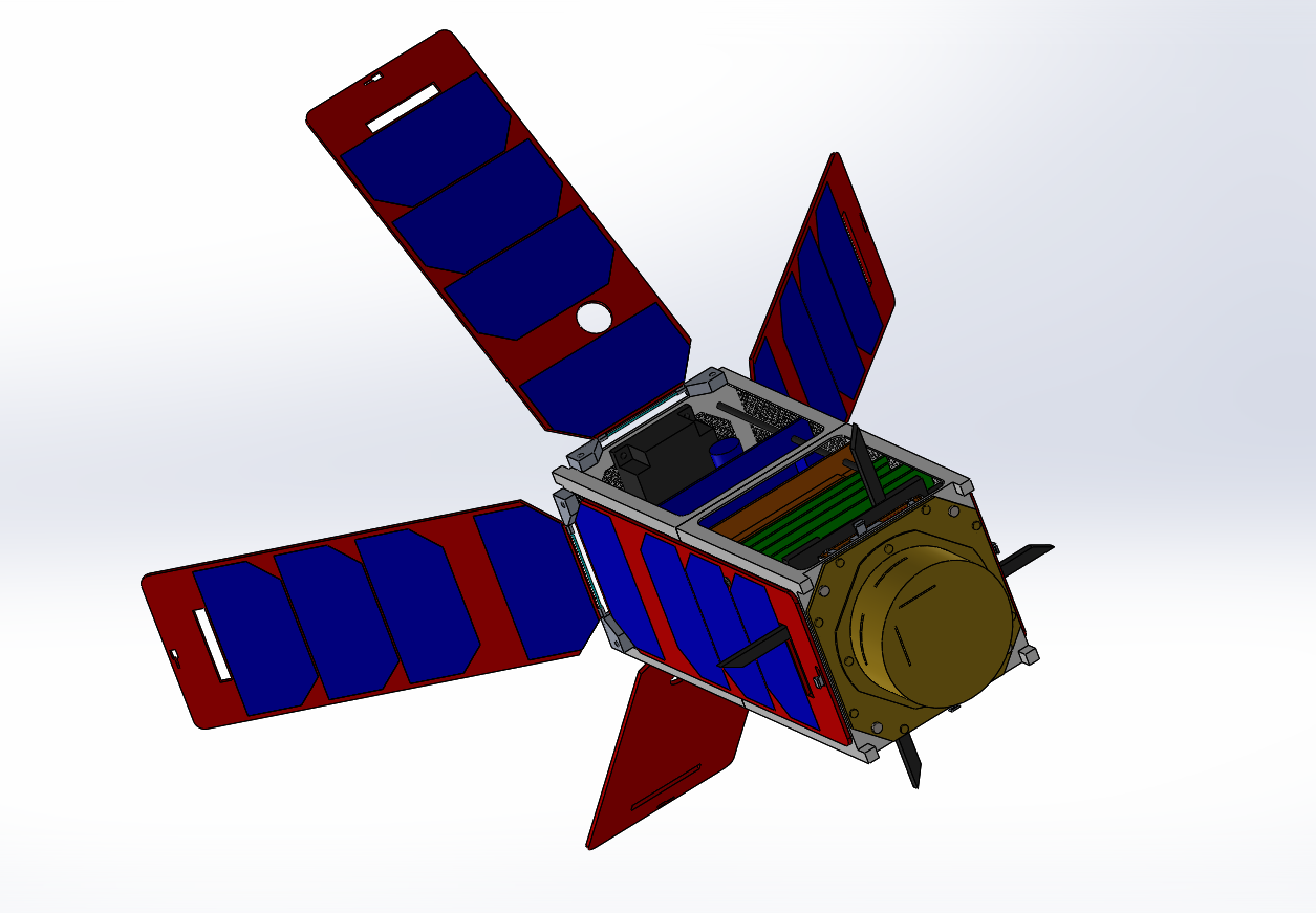
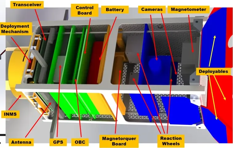
As part of a multidisciplinary spacecraft design project, our team produced the concept for a 2U CubeSat mission to study the thermosphere. It would measure temperature and atmospheric density directly, and infer CO₂ concentration from the carbon ions the molecule dissociates into. The spacecraft also served as a technology demonstrator for deployable solar arrays used for passive attitude stabilisation, a 3D-printed primary structure, and shape-memory-alloy deployment mechanisms. It was sized for deployment from the International Space Station through a NanoRacks deployer, which fixed the starting altitude at around 400 km and capped the mass at 3.6 kg.
The mission was motivated by a prediction of climate-change theory: that rising CO₂ concentrations should cool the thermosphere and, with it, reduce its density. NASA had already gone after the same question with TIMED, comparing atmospheric data from 2002 and 2008. Our concept was intended to add further data towards correlating those climate models.
The project followed a concurrent engineering approach, requiring the close integration of payload, power, thermal, communications, orbital analysis, and attitude control considerations throughout the design process.
My responsibility was the complete design of the Attitude Determination and Control System (ADCS), including pointing requirements definition, disturbance analysis, sensor and actuator selection, and the evaluation of a distinctive passive aerodynamic stabilisation concept.
2. The Challenge: Requirements
The scientific payload could only take meaningful atmospheric measurements if the spacecraft held a fixed attitude relative to its direction of travel. At the same time, the spacecraft had to maximise power generation from its solar arrays while operating within the severe mass, volume, and power constraints of a 2U CubeSat.
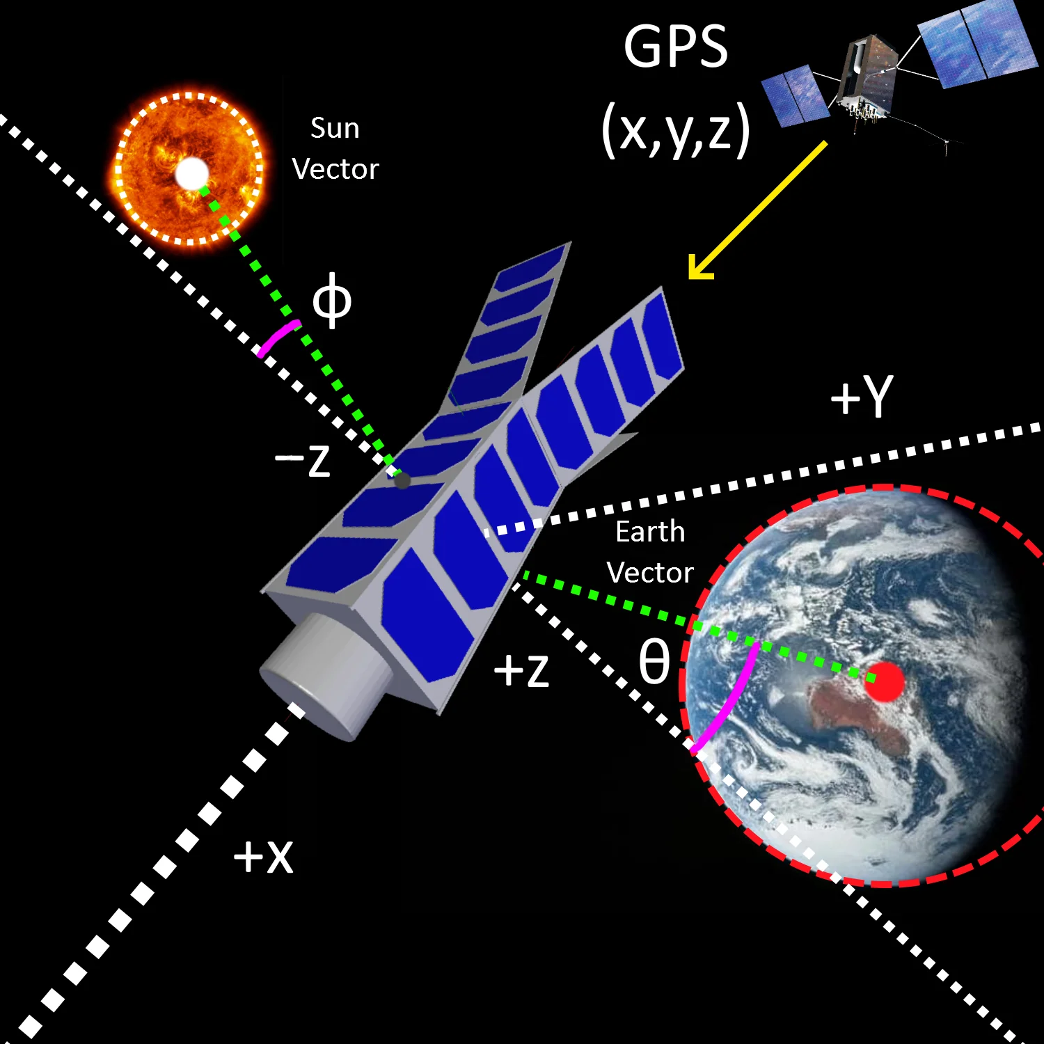
This translated into two distinct pointing requirements. The payload needed the roll axis aligned with the velocity vector. Power generation needed the Z+ axis aligned with the Earth vector, so that the face without solar cells was the one looking down at the planet.
One of the first tasks was defining realistic pointing requirements together with the payload team, establishing the general orientation and error margin needed for the mission. The requirements document originally specified 5°. After consulting a specialist in mass spectrometry to clarify how the payload actually worked, the velocity-vector requirement was tightened to 1°. The Earth-pointing one stayed at 5°, since a solar array loses very little output over a few degrees of misalignment. That 1° became the primary design driver for the entire ADCS architecture.
3. Attitude Determination
Accurate attitude knowledge was essential not only for spacecraft pointing but also for calculating atmospheric density from orbital decay measurements. A pointing tolerance of 1° means the attitude has to be known to better than that, and the rule applied here was a factor of two, giving a knowledge requirement of 0.5°. The proposed sensor suite was selected for both accuracy and redundancy and included:
- A fine Sun sensor and an Earth horizon sensor: two wide-field CMOS cameras facing opposite ways on a single CubeSense board, with attitude processing built in.
- GPS position data, without which the Sun and Earth vectors cannot be resolved into an attitude.
- A three-axis magnetometer as an independent, redundant attitude reference.
- MEMS gyroscopes and accelerometers for attitude propagation during orbital eclipse periods.
- A coarse Sun vector estimation method using solar array power output measurements.
The fine Sun sensor and Earth horizon sensor combination allowed attitude determination with a resolution of approximately 0.2°, comfortably inside the 0.5° knowledge requirement. The magnetometer, combined with GPS data through the International Geomagnetic Reference Field model, gave a coarser cross-check with an accuracy on the order of a few degrees.
The inertial sensors carry a problem of their own. Attitude is recovered by integrating measured rates, so any error in the measurement accumulates and the estimate drifts the longer the spacecraft goes without an absolute fix. The remedy is to recalibrate against the cameras every time the Sun comes back into view. Sampling well above the Nyquist rate keeps each integration step small, while a low-pass filter cuts high-frequency noise and a high-pass filter removes the low-frequency component that feeds the drift.
4. Attitude Control
4.1. Disturbance Analysis
Sizing the control actuators meant first knowing what they would have to fight. I evaluated the four major disturbance sources and estimated their order of magnitude at the CubeSat’s operating altitudes:
- Aerodynamic drag: of the order of 1 μNm at 400 km (beginning of life), rising to 100 μNm at 180 km (end of life).
- Gravity gradient effects: on the order of 10 nNm.
- Solar radiation pressure: approximately 65 nNm.
- Residual magnetic torques: approximately 24 nNm.
Two of these estimates were deliberately pessimistic. Solar radiation pressure was computed assuming a fully reflective spacecraft, since a reflected photon transfers twice the momentum of an absorbed one and the true reflectivity of the surfaces could only be guessed. The magnetic estimate assumes the worst geometry too, with the residual dipole of the magnetorquer cores sitting at right angles to the strongest field the orbit encounters. That maximum occurs at the 51° latitude the ISS inclination reaches.
The results showed that aerodynamic disturbances were by far the dominant effect throughout the mission lifetime, two to four orders of magnitude larger than the remaining disturbances depending on altitude.
This finding ultimately motivated the investigation of aerodynamic stabilisation as a passive attitude control mechanism.
4.2. Passive Aerodynamic Stabilisation
The most unusual part of the design was the study of a passive stabilisation concept inspired by the behaviour of a shuttlecock.
The spacecraft incorporated four deployable fins that acted as aerodynamic control surfaces. Three of them also carried solar cells. The fourth was left bare, since it faces nadir, where cells would spend most of the orbit poorly illuminated. By deploying the panels at an angle, the centre of pressure was shifted away from the centre of mass, generating a restoring aerodynamic moment whenever the spacecraft deviated from its nominal velocity-vector orientation.
This concept allowed the spacecraft to naturally align itself with the velocity vector, reducing the burden on active control elements and minimising power consumption.
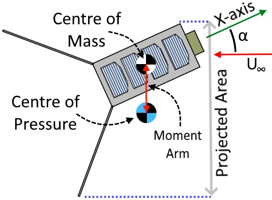
Several deployment angles were analysed. The trade-off is a straight one: a larger angle gives a stiffer restoring moment, but it also presents more frontal area to the flow, and that drag is what eventually brings the satellite down.
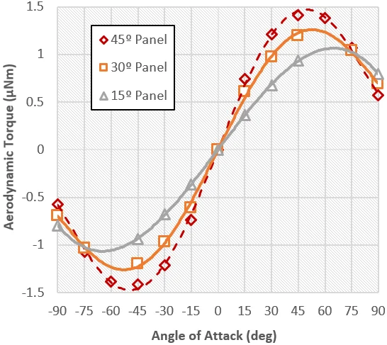
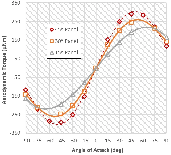
Comparing panel angles directly is awkward, because the torque each one produces depends on altitude through the atmospheric density. To get around this, each configuration was rated by the stiffness of its restoring moment: the moment-versus-angle slope divided by the dynamic pressure. Since dynamic pressure is the only term that varies with height, the resulting figure is constant across the whole orbit and lets the geometries be compared on their own merits. Stiffness rose from 0.0166 at 15° to 0.0214 at 30° and 0.0236 at 45°.
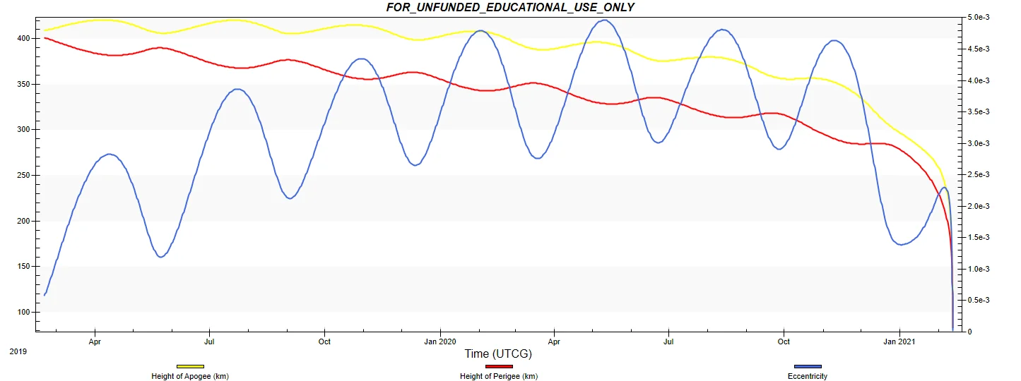
A deployment angle of 45° was selected as the final configuration. It delivered the strongest restoring moment while keeping orbital lifetime within acceptable limits. Simulations performed by the orbital analysis team, using the STK HPOP propagator, estimated a mission lifetime of approximately 152 days (0.42 years) at this deployment angle. This result was cross-checked using an independent lifetime tool, which produced a comparable estimate of 0.53 years, giving confidence in the model.
4.3. Control Actuation
Once the 45° geometry was fixed, the aerodynamic torque could be computed properly rather than estimated: 1.5 μNm at beginning of life, rising to 0.3 mNm at end of life. That end-of-life peak set the bar the actuators had to clear.
While passive stabilisation handled most of the low-frequency disturbance rejection, active actuators were still required for fine pointing and momentum management. And the fins only restore pitch and yaw, leaving roll unactuated. That does not affect the payload requirement, since rotating about the velocity vector leaves that axis pointing where it should, but it does decide which face looks down at the Earth. Holding the Z+ requirement was therefore down to the active actuators alone.
The final architecture combined:
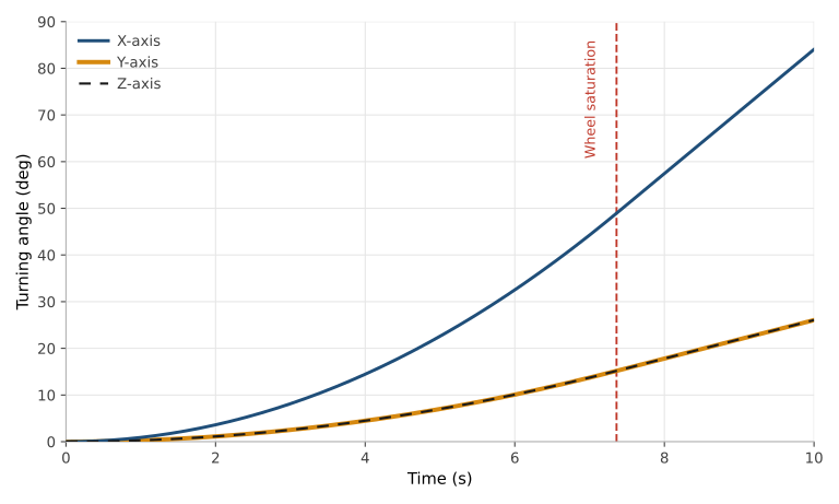
- Three orthogonal reaction wheels, each producing 0.23 mNm of nominal torque and storing up to 1.7 mNms of momentum, which saturates a wheel after about 7.4 seconds of continuous actuation. At 60 g and 80 mW at 2000 rpm they cost little in mass or power, and their 5 rpm speed steps give the resolution needed for fine pointing.
- An ISIS magnetorquer board carrying three coils, ferromagnetic-cored on the Y and Z axes and air-cored on X, each with a nominal dipole of 0.2 Am². These detumble the spacecraft after deployment using a B-dot control law, and dump the momentum the wheels accumulate into the Earth’s magnetic field.
In practice the wheels can swing the CubeSat through 90° in about 14 seconds around the X axis. Around Y and Z it takes closer to 30 seconds, since the moment of inertia there is roughly three times larger. Those are rest-to-rest slews, accelerating through the first half of the angle and braking through the second. The X-axis case comes within a few tenths of a second of saturating its wheel, which is as close to the limit as the design gets.
5. Supporting Analysis and Simulation
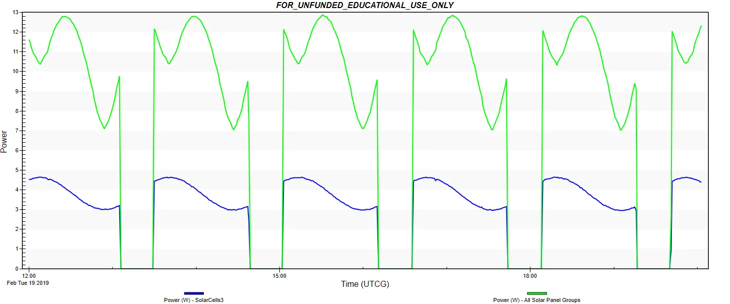
Beyond the ADCS design itself, I also developed the spacecraft geometry used for the solar power simulations. A simplified model was built in SolidWorks and passed through Blender into COLLADA, the format STK reads. Inside Blender the polygons making up each solar cell were separated from the body and grouped by the face they sat on. An auxiliary XML file then declared those groups to STK along with their 29.5% efficiency, so that power output could be plotted face by face across the orbit.
6. Key Takeaways
Looking back, the most valuable aspect of the project was not any individual ADCS calculation, but the exposure to true systems engineering.
Every design decision had consequences across multiple subsystems. Increasing solar array deployment angles improved aerodynamic stability but reduced orbital lifetime. Tightening pointing requirements affected sensor selection, power consumption, and actuator sizing. Mass distribution influenced both structural design and attitude dynamics.
This was my first experience working on a genuinely integrated spacecraft system where performance emerged from the interaction of many interconnected subsystems.